Absolute Rotary Pulse Encoders
/
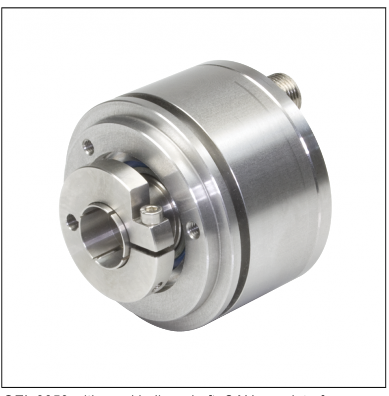
Magnetic Absolute Encoder Gel 2352
Lenord + Bauer Gel 2352General
- Absolute rotary encoder with a maximum total resolution
of 28 bits in a compact design - Encoder series includes single turn variants with up to
16-bit resolution and multiturn variants with up to 12-bit
resolution - Magneto-resistive scanning of a ferromagnetic steel disc
provides unambiguous position values at every angular
position via digital interfaces - Evaluation based on Vernier principle
- Optionally with stainless steel housing
Features
- 28-bit total resolution
- Mechanical gear
- High accuracy ± 0.08°
- Interfaces:
- SSI
- CANopen - Operating temperature -40 °C to +105 °C
- Protection class up to IP 67
Advantages
- Suitable for all standard applications and also for real
heavy-duty applications - Full function in case of condensation: dew-point resistant!
- Extremely resilient housing made of anodised aluminium,
stainless steel variant available - Not affected by dirt or oil mist
- Withstands very high shock and vibration loads as well as
acceleration forces
Field of application
- General mechanical engineering
- Regenerative energies
- Mobile machines
Descripition
Construction and design
The resilient encoder housing with a standard flange size of 58 mm is made of anodised aluminium and can be supplied alternatively in stainless steel.
The double-bearing encoder shaft forms a robust mechanical unit with the metal code disc. The multiturn variant operates with a mechanical gear.
A uniform temperature coefficient on all rotating components ensures the temperature behaviour of the absolute rotary
encoder is stable over the long-term.
Sensing principle
The GEL 2352 is based on contactless magnetic scanning of a ferromagnetic steel code disc, the so-called contour
disc. Magnetoresistive (MR) sensors scan three tracks, delivering corresponding sinusoidal signals. The phase position of the three sinusoidal signals is unambiguous within a single turn. The phase position is evaluated on the Vernier principle, providing the absolute position with high resolution and accuracy.
Interfaces
The absolute rotary encoder supplies the position values either in binary or gray code via a fast synchronous serial interface (SSI) or as per encoder profile DS406 via a CANopen interface.
Temperature ranges
High precision SMD components are used in the absolute rotary encoder. Despite careful selection, thermal ageing of
these components cannot be excluded. For this reason the encoder should be stored at a temperature from -40 °C to
+85 °C.
Operating temperatures of -40 °C to +105 °C are allowed, an installed absolute rotary encoder is not allowed to exceed this temperature range. The function of the absolute rotary encoder is ensured within the operating temperature range allowed, (DIN 32878); here it is the temperature at the en-
coder housing that applies.
The temperature of the absolute rotary encoder is affected by the installation situation (thermal conductance, thermal
radiation), the heating caused by the absolute rotary encoder (bearing friction, electrical power loss) and the ambient
temperature. The operating temperature may be higher than the ambient temperature depending on the operation of the absolute rotary encoder.
Depending on the supply voltage the heating caused by the encoder can be up to 10 °C. At high operating speeds
> 5,000 min-1 the heating caused by the encoder can be up to 20 °C due to the bearing friction. If the absolute rotary encoder is operated close to the limits of the specifications allowed, the ambient temperature must
be reduced by suitable means (cooling) such that the operating temperature range allowed is not exceeded.
Technical Data
| General | ||
| Accuracy | &± 0.08° | |
| Repeatability | < 0.01° | |
| Electrical data | ||
| Operating voltage | 10 to 30 V DC with reverse voltage protection | |
| Power consumption | < 1 W | |
| Resolution single turn | 8, 9, 10, to 16 bit (measuring steps over 360°) | |
| Resolution multiturn | 12 bit (revolutions, mechanical gear) | |
| Interface | SSI (gray / binary), CANopen encoder profile DS406 | |
| Mechanical data | ||
| Moment of inertia of rotor | 611.8 x 10⁻⁶ kgm2 | |
| Material | Aluminium anodised stainless steel 1.4101 |
|
| Weight singleturn | Aluminium: 250 g, stainless steel: 480 g | |
| Weight multiturn | Aluminium: 290 g, stainless steel: 555 g | |
| Operating speed (limit value) | 6,000 min-1 | |
| Operating torque | < 3 Ncm | |
| Bearing life | 105 h at 1,000 min-1 | |
| Shaft sealing ring (option) | Material: Viton, protection class IP 67 / 69K | |
| Ambient data | ||
| Working temperature range | -40 °C to +85 °C | |
| Operating temperature range | -40 °C to +105 °C | |
| Storage temperature range | -40 °C to +85 °C | |
| Protection class | IP 64, IP 67 | |
| Vibration protection (DIN EN 60068-2-6) | 200 m/s2, 10 to 2000 Hz | |
| Shock protection (DIN EN 60068-2-27) | 2000 m/s2, 11 ms | |
| EMC | EN 61000-6-1 to 4 | |
| Insulation strength | Ri > 1 MΏ, at a testing voltage of 500 V AC | |
| Relative humidity of air max. | 99 % | |
| Condensation | permissible | |
| Clamping flange | ||
| Shaft load (radial/axial) | 90 N / 70 N at 1000 min-1 | |
| Synchro flange | ||
| Shaft load (radial/axial) | 90 N / 70 N at 1000 min-1 | |
| Semi hollow shaft | ||
| Shaft load (radial/axial) | 75 N / 70 N at 1000 min-1 | |
Dimensional drawings
Dimensional drawings GEL 2352 - SSI (single turn)

Dimensional drawings
Dimensional drawings GEL 2352 - CANopen

Synchronous serial interface
The synchronous serial interface transfers the position data
at a clock frequency of up to 2 MHz. Prior to further position
sampling, a minimum clock pulse space of 16 μs must be
met.

Principle of the serial data transmission [gray code (25 bits),

RS 422 / RS 485 standard]
f  62.5 kHz
T   Length of the clock signal period (= 1/clock frequency)
Tp Clock pulse space, between the clock sequences TP At least 16 μs
Cable length
With the synchronous serial interface protocol the transmis-
sion rate allowed drops with increasing cable length. A
screened, twisted pair cable is recommended for the signal
cables (± CLOCK and ± DATA).
Direction of rotation
The encoder can output increasing position values on the
clockwise or counter clockwise rotation of the shaft. The di-
rection of rotation can be selected by using the CW/CCW
input (counting direction).

PRESET function
The output signals can be set to a PRESET value from any
position. As supplied the encoder is set to half the maximum
resolution. The PRESET is set electronically if the supply
voltage VS is briefly t > 100 ms applied to the PRESET input
(do NOT apply continuously). Other PRESET values are
available on request.
| pin | signal | Description |
| 1 | GND | Earth |
| 2 | Preset | Electronic adjustment VS, t > 100 ms |
| 3 | DATA- | Output: Differential data signal in accordance with RS 485 |
| 4 | DATA+ | |
| 5 | CLOCK- | Input: Differential clock signal in accordance withRS 485 |
| 6 | CLOCK+ | |
| 7 | VS | Opreating voltage |
| 8 | CW/CCW | Direction of rotation: Default = GND; Inverse =VS |

| Output code | bionar7y Gray |
| Driver | RS 486 compatible |
| Clock frequency | max. 2 MHz |
| Transmission | Max. 1,200 m depending on transmission rate |
| The immunity to interference | high immunity to interference via symmetrical transmission |
| Direction of rotation | adjustable, standard clockwise (CW) with view on the en- coder shaft, increasing position values |
| The immunity to interference | high immunity to interference via symmetrical transmission |
| The immunity to interference | high immunity to interference via symmetrical transmission |
CANopen interface
Pin layout - CANopen
| pin | Bus IN | Bus OUT |
| 1 | CAN_GND | CAN_GND |
| 2 | +VS IN | +VS OUT |
| 3 | GND | GND |
| 4 | CAN_H | CAN_H |
| 5 | CAN_L | CAN_L |

Technical data CANopen
| Device profile | CANopen DS406 with additional function |
| Cable diameter | 8 m |
| Programmable parameters | Resolution, PRESET, offset, counting direction, speed, ac- celeration and rotational speed output, range output referred to pre-defined values, scalable number of steps (decimal/ binary) |
| Output code | Binary |
| Baud rate | 50 kbit/s...1 Mbit/s can be set via bus master |
| Sensor ID | 0...99, can be set via bus master |
| Terminating resistor | To be provided externally |
| Operating temperature | -40...+85 °C (shorttime 100 °C) |
Type code GEL 2352

Customer-specific designs
Customer-specific modifications to mechanical and electrical features are in principle possible.
Restriction of the type code for SSI
| Feature | Possible variant |
| Number of revolutions | 00, single turn |
| Flange, shaft | B, D |
| Electrical interface | 1 |
Restriction of the type code for CANopen interface
| Feature | Possible variant |
| Flange, shaft | E |
| Electrical interface | 2 |
| Material | 2 |
Accessories


Accessories
Ordering overview for mounting accessories
| Description | Item number |
| Torque support, hard(1) | FB 23504 |
| Torque support, soft(1) | FB 23505 |
| Bushing, 8 mm, POM (polyoxymethylene) | RH 23501 |
| Bushing, 10 mm, POM (polyoxymethylene) | RH 23502 |
| Bushing, 12 mm, POM (polyoxymethylene) | RH 23503 |
| Bushing, 8 mm, brass | RH 23504 |
| Bushing, 10 mm, brass | RH 23505 |
| Bushing, 12 mm, brass | RH 23506 |
| Clamping elements (3 pieces) | KL 200 |
| Metal coupling, inside diameter: 5 to 12 mm (state shaft diameter) | MK 8 |
| Metal coupling, inside diameter: 6 to 15 mm (state shaft diameter) | MK 12 |
| Clamp coupling KK14, inside diameter: 6 to 16 mm (state shaft diameter) | KK 14 |
Ordering overview for connection accessories
| Description | Item number |
| Connection cable 10 m, 8-pin M12 socket, straight / flying lead | FS 1352 |
| 8-pin M12 mating connector SSI, straight | FS 1095 |
| M12 mating connector CANopen, 5-pin socket, A-coded | FS 3020 |
| M12 mating connector CANopen, 5-pin plug, A-coded | FS 3021 |
| CANopen connection cable 10 m, 5-pin plug / flying lead with ferrules | BK 2100 |
| CANopen connection cable 2 m, 5-pin plug / flying lead with ferrules | BK 2101 |
| CANopen connection cable 10 m, 5-pin socket / flying lead with ferrules | BK 2102 |
| CANopen connection cable 2 m, 5-pin plug / flying lead with ferrules | BK 2103 |
| CANopen connecting cable 10 m, 5-pin socket/plug | BK 2104 |
| CANopen connecting cable 10 m, 5-pin socket/plug | BK 2103 |
| CANopen terminating resistor M12 | FS 3040 |
-
 Bolt Torque Equipment
-
 Hydraulic Cylinders
-
 Hydraulic - Mechanical Tools
-
 Machine Condition Monitoring
-
 Portable Machine Equipment
-
 Boiler Maintenance
-
 Valve Grinding & Test Machines
-
 Material Handling and Lifting
-
 Industrial Components
-

 Dosing Pumps
-

 Sensor Technologies
-


 JAQUET
-


 Lenord + Bauer
-


 Pruftechnik Vibration sensor
-


 Balluff
-


 Absolute Rotary Pulse Encoders
-

 Cables, Connectors
-
 Chemical Technical Products


