Absolute Rotary Pulse Encoders
/
Rotary Encoder Gel 2351
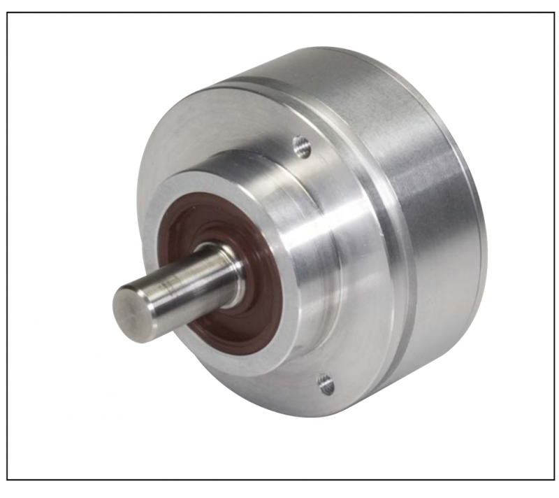
Lenord + Bauer Gel 2351- Single turn absolute rotary encoder with a resolution of 16 bits
- Magneto-resistive scanning of a ferromagnetic steel disc provides unambiguous position values at every angular position via analogue interfaces
- Evaluation based on Vernier principle
- Available with stainless steel or aluminium housing
- Magnetic scanning is not subject to ageing and is resist- ant to temperature fluctuations, contamination or conden- sation
- 16 bit resolution
- High accuracy ± 0,08°
- Analogue interface
- Current output: 4 ... 20 mA
- Voltage output: 0 ... 10 V - Operating temperature -40 °C to 105 °C
- Protection class up to IP 67
- Suitable for all standard applications and also for real heavy-duty applications
- Full function in case of condensation:
dew-point resistant! - Extremely resilient housing made of anodised aluminium, stainless steel variant available
- Not affected by dirt or oil mist
- Withstands very high shock and vibration loads as well as acceleration forces
- Straightforward commissioning using PRESET or teachin function
- Construction machines
- Agricultural machines
- Food industry
- Wind power
- Offshore technology
Description
The resilient encoder housing with a standard flange size of 58 mm is made of anodised aluminium and can be supplied alternatively in stainless steel. The housing is extremely compact and has a housing length of approx. 30 mm.
The device provides a high level of protection against vibration and humidity. For this purpose the electronics are encapsulated. With the shaft sealing ring option the protection class IP 67 is achieved.
The double-bearing encoder shaft forms a robust mechanical unit with the metal code disc.
A uniform temperature coefficient on all rotating components ensures the temperature behaviour of the absolute rotary encoder is stable over the long-term.
Sensing principle
The GEL 2351 is based on contactless magnetic scanning of a ferromagnetic steel code disc, the so-called contour disc. Magnetoresistive (MR) sensors scan three tracks, delivering corresponding sinusoidal signals. The phase position of the three sinusoidal signals is unambiguous within a single turn. The phase position is evaluated on the Vernier principle, providing the absolute position with high resolution and accuracy.
Even if the rotary encoder moves in the de-energised state, the current position value is detected immediately after power is switched on.
Interfaces
The single turn absolute rotary encoders in the GEL 2351 series provide unambiguous angular position values via an analogue interface. A voltage interface from 0 to 10 V DC and a current interface with an output range from 4 to 20 mA are available. By using highly accurate converter blocks the high resolution of the contour disc can also be provided on the analogue interface.

Voltage output signal 0 to 10 V DC

Current output signal 4 to 20 mA
The measuring range, position of the zero point (PRESET) and direction of rotation of the absolute rotary encoder can be adjusted
Temperature ranges
High precision SMD components are used in the absolute rotary encoder. Despite careful selection, thermal ageing of these components cannot be excluded. For this reason the encoder should be stored at a temperature from -40 °C to 85 °C.
Operating temperatures of -40 °C to 105 °C are allowed, an installed absolute rotary encoder is not allowed to exceed this temperature range. The function of the absolute rotary encoder is ensured within the operating temperature range allowed, (DIN 32878); here it is the temperature at the encoder housing that applies.
The temperature of the absolute rotary encoder is affected by the installation situation (thermal conductance, thermal radiation), the heating caused by the absolute rotary encoder (bearing friction, electrical power loss) and the ambient temperature. The operating temperature may be higher than the ambient temperature depending on the operation of the absolute rotary encoder.
Depending on the supply voltage the heating caused by the encoder can be up to 10 °C. At high operating speeds > 5,000 min-1 the heating caused by the encoder can be up to 20 °C due to the bearing friction.
If the absolute rotary encoder is operated close to the limits of the specifications allowed, the ambient temperature must be reduced by suitable means (cooling) such that the operating temperature range allowed is not exceeded.
Technical data
| GEL 2351A | GEL 2351C | |
| General | ||
|---|---|---|
| Repeatability | 0,01° | |
| Accuracy | ± 0,08° | |
| Electrical data | ||
| Operating voltage VS | 15 to 30 V DC with reverse voltage protection | |
| Power consumption | < 1 W (without load) | |
| Output load RL | ≥ 1 kΩ | ≤; (VS - 4 V) / 20 mA |
| Resolution single turn | 16 Bit (0.153 mV) | 16 Bit (0.244 μA) |
| Analogue Interfaces | 0 to 10 V | 0 to 20 mA |
| Linearity | ± 2,44 mV | ± 4,8 μA |
| Temperature drift Typ. | ± 0,34 mV/K Typ. | ± 24μA/K |
| Offset Max. | ± 9 mV Max. | ± 24μA |
| Mechanical Data | ||
| Moment of inertia of rotor | 611.8 x 10⁻⁶ kgm2 | |
| Material | anodised aluminium, stainless steel 1.4104 | |
| Weight | aluminium: 250 g; stainless steel: 390 g | |
| Shaft load (radial/axial) | at 1000 min-1 = 90 N / 70 N, | |
| Operating speed (limit value) | 6,000 min-1 | |
| Operating torque | < 3 Ncm | |
| Bearing life | 105 h at 1,000 min-1 | |
| Shaft sealing ring (optional) | Material: Viton, protection class IP 67 | |
| Ambient data | ||
| Working temperature range -40 °C to 80 °C | -40 °C to 80 °C | |
| Operating temperature range | -40 °C to 105 °C | |
| Storage temperature range | -40 °C to 85 °C | |
| Protection | IP 64, IP 67 | |
| Vibration protection (DIN EN 60068-2-6) | 200 m/s2, 10 to 2000 Hz | |
| Shock protection (DIN EN 60068-2-27) | 2000 m/s2, 11 ms | |
| EMC | EN 61000-6-1 to 4 | |
| Insulation strength (DIN EN 60439-1) | Ri > 1 MΩ, at a testing voltage of 500 V AC | |
| Relative humidity of air max. | 99 % | |
| Condensation | permissible | |
Dimensional drawings
Dimensional drawing GEL 2351

Functions
The encoder can output increasing position values on the clockwise or counter clockwise rotation of the shaft. The direction of rotation can be selected by using the CW/CCW input (counting direction).

PRESET function
With the aid of the PRESET function the measuring range can be adapted to suit the application and the zero point adjusted.
By applying VS for more than 100 ms the middle of the measuring range is set to the actual position of the rotary encoder. This value is saved in the rotary encoder in nonvolatile memory. During commissioning the PRESET function should be used for optimal adjustment of the measuring range.

Teach-in function
The teach-in function is an optional commissioning function of the GEL 2351. Using this function the operating range of the absolute rotary encoder can be restricted to the required range to obtain the full resolution and accuracy in this range. For this purpose the minimum value (Teach-In Min) and the maximum value (Teach-In Max) must be defined. Outside this range the related end value for the measuring range is output. To define the signal, a high signal is applied to the related signal inputs for at least 100 ms on reaching the Teach-In Min and Teach-In Max positions. The range defined is saved in the absolute rotary encoder in non-volatile memory.

Pin layout
Pin assignment
Plug M12, 8-pin

View on the connection side
| Pin | Signal | Explanation |
| 1 | GND | Earth |
| 2 | Preset (1) | Electronic adjustment UB, t > 100 ms Set measuring range zero point or centre |
| 3 | T_Low (2) | Teach-In Min: lower measuring range limit |
| 4 | T_High (2) | Teach-In Max: upper measuring range limit |
| 5 | AOUT | Analogue output (current/voltage) |
| 6 | GNDA | Analogue output earth |
| 7 | UB | Operating voltage |
| 8 | CW/CCW | Direction of rotation: Default = GND; Inverse = VS |
Unused inputs must be connected to GND.
Type code GEL 2351

Customer-specific designs
Customer-specific modifications to mechanical and electrical features are in principle possible.
Accessories


Ordering overview for mounting accessories
| Description | Item number |
| Metal coupling MK 8, inside diameter: 5 to 12 mm (state shaft diameter) | MK 8 |
| Metal coupling MK 12, inside diameter: 6 to 15 mm (state shaft diameter) | MK 12 |
| Clamp coupling KK14, inside diameter: 6 to 16 mm (state shaft diameter) | KK 14 |
| Clamping elements (3 pieces) | KL 200 |
| 8-pin M12 mating connector for analogue interface | FS 1352 |
| Connection cable 10 m, 8-pin M12 socket, straight / flying lead | FS 1095 |
-
 Bolt Torque Equipment
-
 Hydraulic Cylinders
-
 Hydraulic - Mechanical Tools
-
 Machine Condition Monitoring
-
 Portable Machine Equipment
-
 Boiler Maintenance
-
 Valve Grinding & Test Machines
-
 Material Handling and Lifting
-
 Industrial Components
-

 Dosing Pumps
-

 Sensor Technologies
-


 JAQUET
-


 Lenord + Bauer
-


 Pruftechnik Vibration sensor
-


 Balluff
-


 Absolute Rotary Pulse Encoders
-

 Cables, Connectors
-
 Chemical Technical Products


